Collaborative Strategies in Integrated Stamping and Welding Design
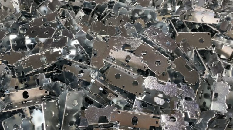
In the field of metal structure manufacturing, stamping and welding are two of the most common fundamental processes. This article systematically introduces the key points, common issues, and optimization approaches of integrated stamping-welding collaborative design, providing practical reference for technical personnel and supply chain managers.
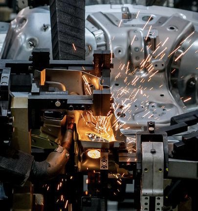
Table of Contents
In-House Tooling Development and Adjustment Capability
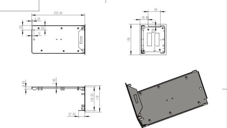
Integrated stamping-welding refers to considering welding process requirements during the stamping part design stage, to ensure that the part’s structure, dimensional accuracy, and positioning references meet the needs of subsequent welding and assembly processes. It emphasizes that “design serves the assembly” rather than operating independently.
In traditional workflows, stamping drawings are often developed solely by product engineers, while welding fixture design and process planning are introduced later. This disconnected approach can easily lead to design misalignment, affecting welding quality and assembly efficiency.

Common Problems in Stamping-Welding Collaboration
The following are the most common manufacturing issues caused by poor stamping-welding collaboration:
Leads to difficulty in achieving high-precision assembly in welding fixtures, affecting overall assembly dimensional consistency.
Causes limited access for welding guns or fixture clamping, and may result in inadequate weld strength.
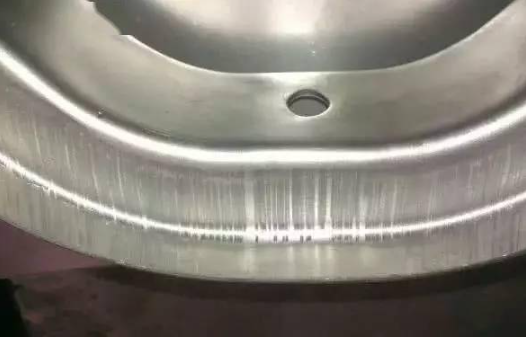
Aggravates welding deformation, unstable weld nuggets, and disrupts automated equipment operation.
Variations in electrical resistance between different material batches result in welding current fluctuations and unstable quality.
Prevent the implementation of automatic positioning, loading/unloading, and automated welding processes, hindering efficiency.
Five Optimization Suggestions for Stamping-Welding Design Collaboration
To achieve a stable and controllable stamping-welding manufacturing process, the following should be considered during the design phase:
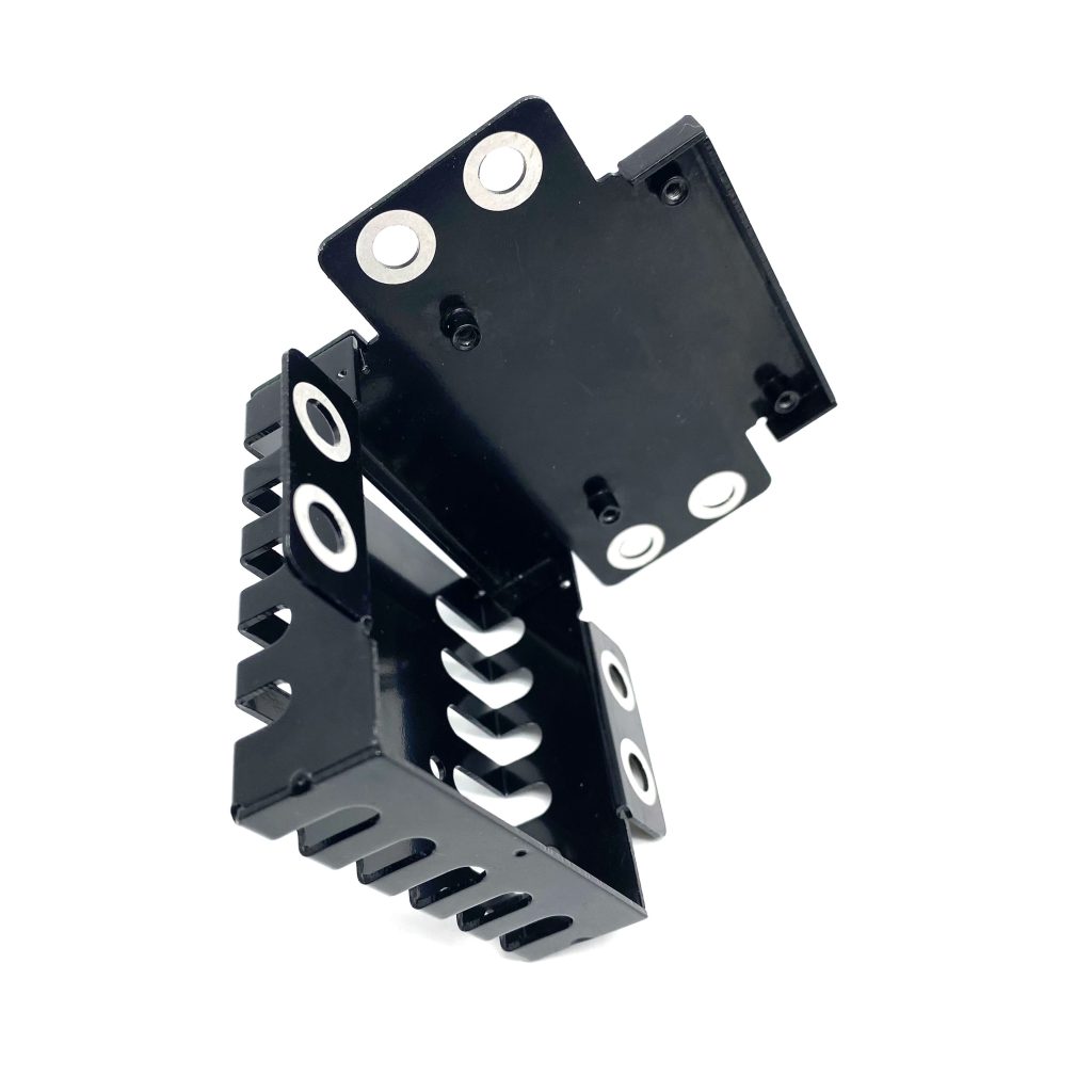
1. Design reasonable locating holes and assembly references
Stamping parts should include locating holes based on fixture requirements, using standard diameters and tolerance ranges to improve assembly consistency.
2. Optimize flange structure to meet welding lap requirements
Leave sufficient space for welding spots and ensure accessibility for welding guns, avoiding misaligned or cold welds due to interference.
3. Control key dimensional tolerances to match welding precision
Clearly define functional dimensions and apply specific tolerances in drawings; apply die compensation when necessary.
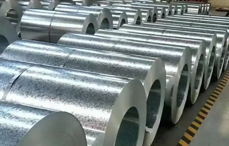
4. Ensure material consistency and surface treatment compatibility
Use the same material grade and coating type to avoid inconsistencies in electrical resistance that can affect welding; also consider the impact of lubricants or coatings.
5. Initiate DFM (Design for Manufacturing) review early
Organize cross-functional reviews among stamping, welding, and fixture engineering teams early in the design stage to prevent repeated changes and rework later.